IntroductionAs a core parameter of enameled copper wire, gauge directly determines product performance and application suitability, playing a fundamental role in ensuring stable operation of electrical equipment and precise control of production costs. The gauge chart is the key tool to help practitioners quickly select the appropriate gauge.
1.1 The Impact of Gauge on Enameled Copper Wire PerformanceCore performance indicators of enameled copper wire, such as conductivity, current-carrying capacity and resistance, are closely related to gauge, which essentially reflects wire diameter. Thicker wires (smaller gauge numbers) have larger cross-sectional areas, lower electron flow resistance, better conductivity and stronger current-carrying capacity; conversely, thinner wires (larger gauge numbers) have smaller cross-sectional areas and higher resistance, which are prone to heating under the same current load and may affect equipment efficiency.
1.2 Common Pain Points Solved by Reliable Gauge ChartsImproper gauge selection often causes problems in practice: using overly thin wires for high-load motor windings may lead to overheating, accelerated insulation aging and even short circuits; overly thick wires result in material waste and may not fit the winding space. A reliable gauge chart avoids these issues by clarifying core parameters of different gauges.
1.3 Target Audience of This GuideThis guide is for electrical engineers, manufacturers, purchasers and electronic DIY enthusiasts. Engineers use it for design and R&D; manufacturers optimize material selection and balance performance and cost; purchasers ensure accurate procurement; DIY enthusiasts find suitable gauges for small projects.
1.4 Overview of Core ContentStarting from basic understanding of enameled copper wire gauge, this article interprets mainstream gauge systems, provides gauge chart references, shares reading and selection methods with practical cases, and answers common questions to help readers master gauge chart application skills.
I. Understanding Enameled Copper Wire Gauge: Core Basic Cognition1.1 What is Gauge?Gauge, or wire specification, is a standard parameter for measuring wire diameter. It is the core identifier for distinguishing enameled copper wire specifications and is directly related to the wire's physical and electrical properties.
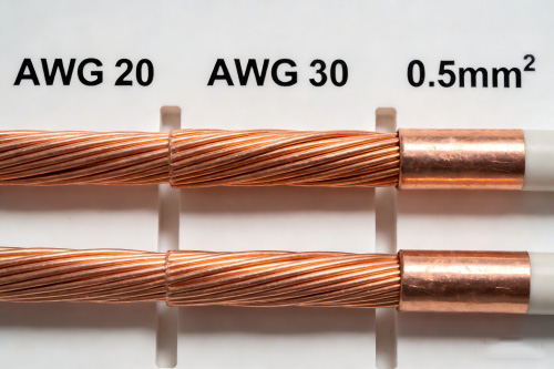
Notably, gauge number and wire size are inversely related: larger gauge numbers mean thinner wires, and smaller numbers mean thicker wires (e.g., AWG 20 wire is much thicker than AWG 30 wire). This relationship is the basic logic for selection.
1.2 Common Enameled Copper Wire Gauge SystemsGlobal enameled copper wire gauge systems vary by region and industry, with three mainstream types: AWG, SWG and metric gauge.
 1.2.1 AWG (American Wire Gauge)
AWG (American Wire Gauge) is widely used in North America and global industrial fields, covering AWG 0000 (thickest) to 40 (thinner) to meet needs from large equipment to small components. Common specifications include AWG 18/UEW, 24/PEW and 30/AIW, which are recognized in motor manufacturing and electronic circuits.
1.2.2 SWG (Standard Wire Gauge)SWG (Standard Wire Gauge) is a traditional system once widely used in Europe and Asia, mainly for old equipment maintenance now. Common specifications include SWG 20/PEW and 26/UEW.
1.2.3 Metric Gauge (mm²)Metric gauge (mm²) uses cross-sectional area as the core identifier, complying with IEC standards and widely used globally. It is intuitive (no need to memorize inverse relationships), with common specifications such as 0.75 mm²/UEW, 1.5 mm²/PEW and 2.5 mm²/AIW, suitable for new energy and home appliances.
1.2.4 Comparison of Mainstream Gauge SystemsCross-system conversion is common in practice (e.g., AWG 20/UEW ≈ SWG 22/PEW ≈ 0.5 mm²; 0.75 mm²/UEW ≈ AWG 18/UEW), but it is only an approximate reference. Formal selection must be based on target system parameters.
1.3 Key Parameters in Enameled Copper Wire Gauge ChartA complete enameled copper wire gauge chart contains core parameters that are key for selection and need accurate understanding.
1.3.1 Gauge Number (AWG/SWG/Metric)Gauge number is the core identifier of the chart, clearly indicating the gauge system and specifications (e.g., "
AWG 25", "SWG 20", "1.0 mm²"), which is the primary basis for finding parameters.
1.3.2 Nominal Diameter (Bare Wire and Enameled Wire)Nominal diameter includes bare wire (copper conductor without insulation) and enameled wire (overall diameter with insulation). Enameled wire diameter directly affects winding space utilization; ignoring insulation thickness may prevent the wire from being embedded into the slot.
1.3.3 Cross-Sectional Area (mm²)Cross-sectional area determines current-carrying capacity and resistance: larger area means stronger current-carrying capacity and lower resistance. Metric gauge marks it directly, while AWG and SWG charts also indicate it for easy comparison.
1.3.4 Current-Carrying Capacity (Amperes, Based on Insulation Class and Ambient Temperature)Current-carrying capacity (A) is the maximum continuous current under safe operation, greatly affected by insulation class and ambient temperature: higher insulation class and lower ambient temperature mean stronger current-carrying capacity. Charts mark values under different conditions for selection.
1.3.5 Resistance (Ohms per Meter/Foot at 20°C)Resistance (Ω/m or Ω/ft at 20°C) is inversely proportional to cross-sectional area. It is critical for calculating circuit loss and evaluating heating, especially for high-precision equipment and long-distance applications.
1.3.6 Weight per Unit Length (Kilograms per Kilometer or Pounds per 1000 Feet)Weight per unit length (kg/km or lbs/1000ft) reflects material consumption, used for cost accounting and transportation planning (e.g., calculating total consumption for bulk procurement).
1.3.7 Insulation Thickness and TypeInsulation thickness affects enameled wire diameter and performance. Common types include UEW (good solderability for small components), PEW and AIW (excellent high-temperature resistance). Charts mark thickness and type for working condition matching.
 II. Enameled Copper Wire Gauge Chart: Comprehensive Reference Guide2.1 AWG Enameled Copper Wire Gauge Chart (Most Commonly Used)
AWG is the most widely used standard for enameled copper wire, with charts covering AWG 10-40, basically meeting the needs of most motors and electronic equipment.
2.1.1 Core Range of the Chart: AWG 10 to AWG 40AWG 10-40 is the mainstream industrial range: AWG 10-16 (thick) for large motors/transformers; AWG 18-28 (medium) for small/medium motors and home appliance windings; AWG 30-40 (thin) for small components and precision instruments.
2.1.2 Detailed Explanation of Key Data PointsAWG 10-40 charts include complete parameters: bare wire diameter decreases from 2.588 mm (AWG 10) to 0.080 mm (AWG 40); enameled wire diameter is 0.02-0.10 mm larger than bare wire (e.g., AWG 22/UEW ≈ 0.64 mm, AWG 28/AIW ≈ 0.35 mm); cross-sectional area decreases from 5.26 mm² to 0.0051 mm²; current-carrying capacity (105°C, 25°C) decreases from 30 A (AWG 10) to 0.3 A (AWG 40); resistance increases from 0.0033 Ω/m to 0.401 Ω/m; weight per unit length decreases from 47.4 kg/km to 0.046 kg/km.
2.1.3 Explanation of Current-Carrying Capacity ChangesCharted current-carrying capacity is a reference, changing with ambient temperature and ventilation. For example, at 40°C (105°C insulation), it decreases by ~15%; poor ventilation requires further reduction to avoid overheating.
2.2 SWG Enameled Copper Wire Gauge ChartSWG application is narrowing but still used in specific fields, with unique core specifications and application scenarios.
2.2.1 Relevant SWG Range for Enameled Copper Wire ApplicationsSWG 8-36 is suitable for enameled copper wire: SWG 8-14 (thick) for old industrial motors/transformers; SWG 16-28 for small/medium traditional equipment; SWG 30-36 for traditional electronic components.
2.2.2 Corresponding Core ParametersSWG chart parameters are similar to AWG (diameter, cross-sectional area, current-carrying capacity, etc.). Examples: SWG 20/PEW (bare wire 0.914 mm, area 0.659 mm², current-carrying 4.5 A, resistance 0.027 Ω/m, weight 5.94 kg/km); SWG 28/UEW (bare wire 0.376 mm, area 0.112 mm², current-carrying 1.2 A).
2.3 Metric (mm²) Enameled Copper Wire Gauge ChartMetric gauge is intuitive and compliant with international standards, with charts covering 0.05-10 mm² for most global equipment.
2.3.1 Common Metric Specifications: 0.05 mm² to 10 mm²0.05-10 mm² is the mainstream metric range: 0.05-0.2 mm² (thin) for precision components/micro motors; 0.3-2.5 mm² (medium) for home appliances/small motors; 4-10 mm² (thick) for large motors/industrial transformers.
2.3.2 Parameter Matching with Industrial Standards (IEC 60317)Metric parameters comply with IEC 60317 for manufacturer compatibility. Examples: 1.0 mm²/PEW (bare wire 1.128 mm, enameled wire deviation ±0.03 mm, resistance ≤0.0178 Ω/m, 155°C current-carrying ~10 A); 2.5 mm²/AIW (bare wire 1.784 mm, enameled wire ~1.86 mm, current-carrying 15 A).
2.4 Gauge Conversion Chart (AWG ↔ SWG ↔ Metric)Cross-system selection often requires conversion charts, which provide approximate references but cannot be used as formal selection basis due to errors.
2.4.1 Cross-System Quick ReferenceConversion charts show approximate correspondences: AWG 20 ≈ SWG 22 ≈ 0.5 mm²; AWG 18 ≈ SWG 20 ≈ 0.75 mm²; AWG 26 ≈ SWG 28 ≈ 0.15 mm², facilitating preliminary design and data query.
2.4.2 Conversion Notes (Avoiding Selection Errors)Cross-system conversion has errors: 1) It is only an approximate reference; formal selection must be based on target system parameters. 2) Check bare and enameled wire diameters to avoid space mismatch. 3) Key equipment (precision motors, high-voltage devices) should use the designed gauge system directly.
 III. How to Efficiently Read and Use Enameled Copper Wire Gauge Chart3.1 Step-by-Step Guide to Reading Gauge Chart
Correct chart reading follows the logic: "clarify system → locate parameters → combine working conditions".
3.1.1 Step 1: Determine the Target Gauge System According to Application Scenario and RegionFirst, determine the system based on application region and standards: AWG for North America; SWG for old European/Asian equipment maintenance; metric for global equipment/IEC standards (e.g., AWG for motors exported to the US).
3.1.2 Step 2: Locate Core Parameters (Screen as Needed)Screen key parameters by equipment needs: focus on current-carrying capacity/area for high-current equipment; enameled wire diameter for limited winding space; resistance for high-precision circuits (e.g., small DC motor selection requires both current-carrying capacity and diameter matching).
3.1.3 Step 3: Correct Parameters Combined with Insulation ClassCharted parameters are based on specific insulation classes and need correction. For example, 105°C insulation current-carrying 5 A can increase by ~20% with 155°C insulation, or decrease with 75°C insulation at the same ambient temperature.
3.2 Key Considerations for Selection Using Gauge ChartSelection requires combining chart parameters with equipment working conditions and comprehensive consideration of multiple factors.
3.2.1 Application TypeDifferent applications have distinct requirements: motor windings focus on current-carrying capacity, diameter and insulation high-temperature resistance; transformers balance current-carrying capacity and resistance; electronic components prioritize thinness and precision; automotive wires need vibration/chemical resistance (e.g., high insulation class for new energy vehicle motors).
3.2.2 Temperature EnvironmentAmbient temperature affects current-carrying capacity and service life: select higher insulation class and reduce expected current-carrying capacity for long-term high-temperature operation; relax standards appropriately for low-temperature environments (ensure insulation does not become brittle).
3.2.3 Current Demand (Continuous Load vs. Intermittent Load)Current load is divided into continuous (long-term power-on, follow charted continuous current-carrying capacity strictly) and intermittent (alternating power-on/off, can appropriately increase capacity but control cycle to avoid excessive heating, e.g., thinner wires for intermittent small pneumatic tools).
3.2.4 Space ConstraintsEquipment internal space limits enameled wire diameter: select thin wires for narrow spaces (ensure current-carrying capacity); thicken appropriately for sufficient space to improve stability (e.g., AWG 30+ for micro fan motor windings).
3.2.5 Insulation CompatibilityInsulation compatibility must match working conditions: chemical-resistant insulation (e.g., AIW) for corrosive environments; high-voltage insulation for high-voltage equipment; solderable UEW for small components.
3.3 Practical Cases of Selection Using Gauge ChartPractical cases help clarify chart usage and avoid misunderstandings.
Case 1: Selection of Enameled Copper Wire for Small DC Motor (AWG 28 vs AWG 30)Small DC motor: rated current 0.8 A, ambient 30°C, max enameled wire diameter 0.35 mm. AWG 28/UEW (0.32 mm, 1.0 A) meets requirements; AWG 30/PEW (0.28 mm, 0.7 A) does not. Select AWG 28/UEW.
Case 2: Selection of Enameled Copper Wire for Transformer Winding (Metric 1.5 mm² vs 2.5 mm²)Power frequency transformer: rated current 8 A, ambient 40°C, low resistance loss required. 1.5 mm²/PEW (7.5 A) is insufficient; 2.5 mm²/AIW (11 A, lower resistance 0.0071 Ω/m) meets needs. Select 2.5 mm²/AIW.
Case 3: Selection of Enameled Copper Wire for PCB Inductor (AWG 36)PCB inductor: rated current 0.2 A, narrow space, good insulation required. AWG 36/UEW (0.15 mm, 0.3 A) meets current and space needs. Select AWG 36/UEW.
IV. Common Mistakes to Avoid When Using Enameled Copper Wire Gauge ChartCommon selection mistakes using gauge charts may affect equipment operation and need to be avoided.
4.1 Confusing Bare Wire Diameter with Enameled Wire DiameterConfusing bare and enameled wire diameters: e.g., motor slot max diameter 0.5 mm, AWG 24/AIW (bare 0.45 mm, enameled 0.51 mm) exceeds limit. Use enameled wire diameter for space adaptation.
4.2 Ignoring Temperature Class When Referring to Current-Carrying CapacityIgnoring temperature class for current-carrying capacity: e.g., 105°C/25°C current-carrying 5 A drops to 3 A at 50°C with 75°C insulation, leading to overheating and insulation failure if loaded at 5 A.
4.3 Using the Wrong Gauge SystemUsing wrong gauge system: e.g., AWG for European standard equipment causes parameter mismatch. Clarify equipment gauge system requirements first.
4.4 Overlooking the Impact of Resistance on Power LossOverlooking resistance impact on power loss: e.g., AWG 30/PEW (0.103 Ω/m) replaces AWG 28/PEW (0.064 Ω/m) for continuous motors, increasing resistance by ~61% and power loss significantly.
4.5 Not Distinguishing Between Intermittent Load and Continuous LoadConfusing intermittent and continuous load capacity: over-selecting for intermittent equipment wastes materials; under-selecting for continuous equipment causes overheating and shortens service life.
V. Frequently Asked Questions (FAQs) About Enameled Copper Wire Gauge ChartQ1: What is the Most Common Gauge for Enameled Copper Wire Used in Motors?Motor wire gauge varies by power: small/micro motors (<100 W): AWG 28-36/PEW/UEW or 0.08-0.2 mm²; small/medium motors (100 W-10 kW): AWG 18-28/PEW/AIW or 0.3-2.5 mm² (mainstream: AWG 22-26/PEW/UEW or 0.5-1.5 mm²); large motors (>10 kW): AWG 10-18/AIW or 4-10 mm².
Q2: How Does Insulation Type Affect Gauge Chart Parameters?Insulation type affects parameters via thickness and high-temperature resistance: 1) Thickness varies (UEW 0.02-0.05 mm, AIW 0.03-0.08 mm), changing enameled wire diameter. 2) Higher temperature resistance means stronger current-carrying capacity (e.g., AWG 24/PEW: 3.5 A vs AIW: 4.2 A at 105°C).
Q3: Can AWG Gauge Chart Be Used Instead of SWG Gauge Chart for Selection?AWG should not replace SWG directly due to parameter differences (e.g., AWG 20/UEW: 5 A vs SWG 22/PEW: 4.2 A), which may cause equipment failure. Use AWG only as a preliminary reference.
Q4: Why Does Current-Carrying Capacity Decrease with Larger Gauge Numbers?Larger gauge numbers mean smaller cross-sectional areas, narrower electron flow channels, higher resistance and lower current-carrying capacity (e.g., AWG 30/PEW: 0.050 mm², 0.7 A vs AWG 20/UEW: 0.518 mm², 5 A).
Q5: Where Can I Find a Reliable Enameled Copper Wire Gauge Chart for Industrial Use?Reliable industrial gauge charts are available from: 1) IEC (IEC 60317 for metric) and NEMA (NEMA MW1000 for AWG) official websites. 2) Formal manufacturer websites (mark specific parameters). 3) Professional handbooks (e.g., "Electrical Engineer's Handbook").