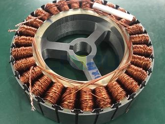
What is Magnet Wire and Its Core Role in MotorsMagnet wire, also known as enamelled wire, is a conductive metal wire coated with an insulating layer on its surface, and it is the core component of motor windings. When a motor operates, the magnet wire windings generate a magnetic field through current to drive the rotor to rotate, and its performance directly determines the energy conversion efficiency and operational stability of the motor. Whether it is an industrial drive motor, an automotive starter motor, or a household appliance motor, magnet wire is like the "heart blood vessels", undertaking the important task of converting electrical energy and magnetic energy.
 The Impact of Proper Magnet Wire Selection on Motors
Properly selected magnet wire enables the motor to operate efficiently under rated conditions, reduces energy loss, and improves heat dissipation performance and service life. On the contrary, improper selection can lead to frequent motor overheating, low efficiency, increased noise, and in severe cases, insulation breakdown and winding burnout, resulting in premature motor failure and increased equipment maintenance costs and downtime losses.
Article Guide: Core Elements and Step-by-Step Selection MethodThis article will break down the key points of selection from the dimensions of magnet wire basic parameters, motor operating conditions, and application scenarios, and provide a practical step-by-step selection method to help motor production, maintenance, and purchasing personnel accurately select suitable magnet wire and avoid selection risks.
I. Master the Basic Parameters of Magnet Wire1.1 Conductor Material: Core Guarantee of ConductivityConductor material directly determines the conductivity, heat resistance, and cost of magnet wire, and is the primary consideration for selection. Currently, the mainstream materials are divided into copper, aluminum, and copper-clad aluminum.
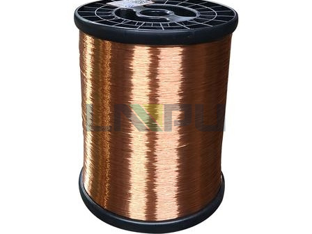
Copper Wire: Preferred for High-Performance ScenariosEnameled Round Copper wire has extremely high conductivity, excellent heat resistance, and ductility. It can maintain stable performance under high-temperature and high-load conditions, and has good solderability, facilitating winding processing. It is suitable for most motors, especially indispensable in high-performance precision motors, industrial heavy-load motors, and other scenarios with high requirements for efficiency and reliability. However, the cost of copper wire is relatively high, which will increase the motor manufacturing cost to a certain extent.
 Aluminum Wire: Cost-Effective Option
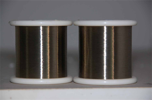
The core advantages of aluminum wire are low cost and light weight, making it suitable for motor scenarios with limited budget, low power, and light load, such as small fan motors and simple water pump motors. However, it has obvious disadvantages: its conductivity is only about 60% of that of copper wire, it is difficult to solder, has a high thermal expansion coefficient, and is prone to joint loosening, oxidation, and other problems after long-term use, with a service life generally shorter than that of copper wire.
 Copper-Clad Aluminum (CCA) Wire: Compromise Solution
Copper-clad aluminum wire uses aluminum as the base material and is coated with a layer of copper on the surface. It combines the cost advantage of aluminum wire and the conductivity of copper wire, with higher conductivity than pure aluminum wire and lower weight than pure copper wire. It is suitable for scenarios that require a balance between cost and performance, such as medium-sized ventilators and ordinary household appliance motors, but is still not as applicable as pure copper wire in high-temperature, high-frequency, and high-reliability scenarios.
Selection Tip: Match Material to RequirementsSelection should be comprehensively judged based on motor power, operating conditions, and budget: copper wire is preferred for high-load, high-temperature, and precision motors; aluminum wire can be used for low-power and low-cost motors; copper-clad aluminum wire can be considered for scenarios requiring a balance between cost and performance.
1.2 Wire Gauge (Cross-Sectional Area): Key to Current-Carrying CapacityRelationship Between Wire Gauge and ConductivityThe wire gauge of magnet wire directly determines its current-carrying capacity and resistance: the thicker the wire gauge, the smaller the resistance, the stronger the current-carrying capacity, and the better the heat dissipation performance; the thinner the wire gauge, the larger the resistance, which is prone to performance degradation due to heating, but can save winding space and adapt to small motors.
Basis for Wire Gauge CalculationWire gauge selection needs to be comprehensively calculated based on the motor's rated current, power, and winding space: first, calculate the rated current according to the motor power and voltage, then determine the maximum wire gauge that can be accommodated in combination with the insulation layer thickness and winding slot volume, while reserving a certain heat dissipation space. For example, a 1.5kW three-phase asynchronous motor with a rated current of about 3A usually uses magnet wire with a wire gauge of 1.0-1.2mm².
Standard Wire Gauge Systems and ConversionCurrently, the mainstream wire gauge standards in the industry are AWG (American Wire Gauge) and mm² (square millimeter), and attention should be paid to conversion and adaptation. For example, AWG 18 wire corresponds to a wire diameter of about 0.82mm, and AWG 16 wire corresponds to a wire diameter of about 1.02mm. In actual selection, it is necessary to comply with the standard requirements of the motor design drawings.
Risks of Improper Wire Gauge SelectionAn undersized wire gauge will lead to excessive winding resistance and severe heating during operation, which not only reduces motor efficiency but also accelerates insulation layer aging; an oversized wire gauge will occupy too much winding space, resulting in insufficient number of turns, affecting motor magnetic field strength, and increasing motor volume and cost.
1.3 Insulation Material and Heat Resistance Class: Core of Insulation ProtectionCore Role of Insulation LayerThe core function of the magnet wire insulation layer is to achieve electrical isolation between windings, while resisting external influences such as high temperature, mechanical wear, and chemical corrosion, ensuring the safe and stable operation of the motor. The performance of the insulation layer directly determines the maximum allowable operating temperature and service life of the motor.
Mainstream Insulation Materials and Their CharacteristicsDifferent insulation materials have significant differences in heat resistance, corrosion resistance, and mechanical strength, and are suitable for different scenarios:
Polyester (PE): A general-purpose insulation material with low cost and a heat resistance class of 130°C. It is suitable for indoor low-temperature, light-load motors, such as small fan motors and desk lamp motors.
Polyesterimide (PEI): With a heat resistance class increased to 155°C, it has good chemical stability and mechanical strength, and excellent oil and solvent resistance. It is the mainstream choice for industrial motors and is widely used in water pump and compressor motors.
Polyamide-Imide (PAI): With a heat resistance class of over 180°C, it has high mechanical strength and outstanding wear resistance and moisture resistance. It is suitable for motors in high-temperature, humid, and corrosive environments, such as chemical equipment motors and motors around automotive engines.
Polyimide (PI): An extreme heat-resistant material with a heat resistance class of over 200°C and radiation resistance. It is suitable for special motors with high performance requirements in aerospace, medical equipment, and high-end new energy vehicles.
Modified Composite Materials: Such as PEI+PAI double-layer insulation, which combines the advantages of the two materials, has both high heat resistance and wear resistance, and is suitable for motors under high-speed and high-vibration conditions.
.jpg) Matching Insulation Class with Motor Operating Temperature
Matching Insulation Class with Motor Operating TemperatureThe insulation class must be higher than the maximum winding temperature of the motor during operation (ambient temperature + winding temperature rise), usually with a safety margin of 10-20°C. For example, if the ambient temperature of an industrial workshop is about 40°C and the motor winding temperature rise is about 80°C, magnet wire with a heat resistance class of 155°C or higher should be selected.
Considerations for Insulation Layer ThicknessThe thickness of the insulation layer needs to balance electrical insulation performance and winding density: a thick insulation layer can improve dielectric strength and reduce the risk of breakdown, but it will occupy winding space and reduce the number of turns; a thin insulation layer can improve winding density and motor efficiency, but has higher requirements for the performance of the insulation material, and is suitable for small and high-efficiency motors.
II. Select Based on Specific Motor Operating Conditions2.1 Operating Temperature: Core Factor Determining Insulation ClassMotor operating temperature includes ambient temperature and winding temperature rise, which is the key basis for selecting the insulation class. For ordinary motors in indoor normal temperature environments (25-40°C), magnet wire with a heat resistance class of 130-155°C is sufficient; for high-temperature environments (such as metallurgical and chemical workshops with temperatures above 50°C) or high-load motors, magnet wire with a heat resistance class of 180°C or higher must be selected.
At the same time, winding temperature rise should be considered: motors operating continuously have higher winding temperature rise and require magnet wire with a higher heat resistance class; motors operating intermittently have lower temperature rise, and the insulation class can be appropriately reduced to control costs.
2.2 Voltage Requirements: Related to Insulation Strength and ThicknessThe rated voltage of the motor directly affects the dielectric strength requirements of the magnet wire insulation layer: high-voltage motors (such as 10kV industrial motors) require magnet wire with a thick insulation layer or special dielectric materials to prevent insulation breakdown; low-voltage motors (such as 220V/380V civil motors) can use magnet wire with a conventional thickness insulation layer to balance cost and efficiency.
For special scenarios such as new energy vehicle motors and high-frequency high-voltage motors, the corona resistance of the insulation layer must also be considered to avoid insulation layer aging and failure under high-frequency voltage.
2.3 Load and Duty Cycle: Affecting Conductor and Insulation SelectionContinuous-load motors (such as water pumps and conveyor motors) need to operate stably for a long time, and the windings generate heat continuously. Copper wire with high heat resistance insulation should be selected, and the wire gauge should have sufficient margin; intermittent-load motors (such as machine tool spindle motors and starter motors) have short heating cycles, and the wire gauge specification or insulation class can be appropriately reduced to control costs.
High-load motors (such as heavy-duty crane motors) require thick-gauge copper wire and magnet wire with heat resistance class above 180°C to ensure current-carrying capacity and heat dissipation performance; low-load motors (such as small fan motors) can use aluminum wire or copper-clad aluminum wire to reduce costs.
2.4 Environmental Factors: Key to Resisting External ErosionHumidity and MoistureFor motors in humid environments (such as outdoor and aquatic product processing workshops), magnet wire with excellent moisture resistance should be selected, such as PAI insulation and sealed insulation magnet wire, to prevent the insulation layer from absorbing moisture and aging, which may cause short circuits.
Chemical CorrosionFor industrial motors exposed to oil stains, solvents, and corrosive gases, magnet wire with chemical corrosion-resistant insulation materials should be selected, such as PEI and PAI, to avoid insulation layer erosion and damage.
Dust and VibrationFor scenarios with a lot of dust (such as mining equipment motors), magnet wire with strong mechanical wear resistance should be selected; for high-vibration motors (such as vibrating screen motors), stranded magnet wire with strong insulation layer adhesion and good flexibility should be selected to prevent insulation layer shedding caused by winding vibration.
III. Precise Selection by Motor Type and Application Scenario3.1 Differential Selection for AC Motors and DC MotorsAC Motors (Induction Motors, Synchronous Motors)AC motors operate at high frequencies and are prone to skin effect, so stranded magnet wire should be selected to reduce losses; industrial-grade AC motors prefer copper wire with 155-180°C heat resistance insulation; small household AC motors can use copper-clad aluminum wire or aluminum wire to control costs.
DC Motors (Brushed, Brushless BLDC)Brushless DC motors (BLDC) have high requirements for high-frequency performance, so fine-stranded copper wire with PI or PAI insulation is preferred; brushed DC motors have brush wear, so magnet wire with high insulation resistance should be selected to avoid winding short circuits caused by brush powder.
3.2 Industrial Motors: Focus on Durability and EfficiencyIndustrial motors (water pumps, compressors, machine tool motors) are generally under high-load and continuous operation conditions, and the core of selection is reliability and efficiency. It is recommended to select copper conductor, insulation with heat resistance class above 155°C (PEI/PAI), and stranded magnet wire. The wire gauge should reserve a margin of 1.2 times the rated current, and at the same time meet industrial standards such as IEC and NEMA.
3.3 Automotive Motors: Adapt to Extreme ConditionsAutomotive motors (starter motors, generators, new energy vehicle drive motors) need to withstand extreme temperatures of -40°C to 180°C, severe vibration, and oil erosion, with strict selection requirements. It is recommended to select copper wire and PI/PAI composite insulation magnet wire. The insulation layer must have vibration resistance, oil resistance, and high-voltage resistance. New energy vehicle drive motors also need to meet high-voltage insulation (such as 800V) and corona resistance requirements.
3.4 Household Appliance Motors: Balance Cost and PerformanceHousehold appliance motors (refrigerators, washing machines, fans) are sensitive to cost and operate under mild conditions, so the core of selection is cost-effectiveness. Ordinary fan and desk lamp motors can use aluminum wire with PE insulation; washing machine and refrigerator motors are recommended to use copper-clad aluminum wire or copper wire with PEI insulation to balance durability and cost.
3.5 High-Precision and Special Motors: Ultimate Performance AdaptationHigh-precision motors in aerospace, medical, and robotics fields need to meet the requirements of lightweight, high temperature, low noise, and high reliability. It is recommended to select PI insulation and fine-stranded copper wire magnet wire; copper-clad aluminum wire can be used in some lightweight scenarios; micro motors (such as medical device micro motors) need to use fine-diameter and thin-insulation magnet wire to adapt to narrow winding spaces.
IV. Other Key Selection Factors4.1 Compatibility with Winding ProcessThe flexibility of magnet wire must match the winding process: automatic winding machines have high speed and high winding density, so stranded magnet wire with good flexibility and strong insulation layer adhesion should be selected to prevent insulation layer shedding during winding; solid magnet wire can be used for manual winding to reduce processing difficulty.
High-speed winding processes have higher requirements for the wear resistance of the insulation layer, so modified composite insulation magnet wire is recommended to improve wear resistance.
4.2 Heat Dissipation Performance: Affecting Stable Motor OperationThe heat dissipation performance of magnet wire is closely related to conductor material, wire gauge, and insulation layer material: copper wire has better heat dissipation efficiency than aluminum wire, and thick wire gauge is better than thin wire gauge; some special insulation materials (such as modified PI) have stronger thermal conductivity, which can accelerate the heat transfer from windings to the motor housing.
For enclosed motors (without cooling fans), magnet wire with high thermal conductivity should be preferred, and the wire gauge should be appropriately increased to improve heat dissipation margin.
4.3 Cost and Supply CapacitySelection needs to balance performance and budget: copper wire with high-grade insulation should be selected for high-performance scenarios to ensure quality; aluminum wire, copper-clad aluminum wire, or low-grade insulation magnet wire can be used for cost-sensitive scenarios. At the same time, supply stability should be considered: standard specification magnet wire has a short delivery cycle, and for customized specifications (such as special wire gauge and insulation material), the delivery cycle and minimum order quantity should be confirmed in advance.
4.4 Industry Standards and CertificationsMagnet wire selection must comply with corresponding industry standards. For example, industrial motors must meet IEC 60317 and UL 1441 standards, automotive motors must meet ISO and SAE standards, and medical motors must meet biocompatibility certifications. Compliant magnet wire can ensure the safety and reliability of the motor and avoid market access risks.
V. Step-by-Step Guide to Magnet Wire SelectionStep 1: Clarify Core Motor ParametersFirst, determine the motor's rated power, voltage, current, maximum operating temperature, and duty cycle (continuous/intermittent), which are the basic basis for subsequent selection. For example, confirm that the motor is 1.5kW, 380V, 3A, continuously operating, with a maximum ambient temperature of 40°C.
Step 2: Evaluate Operating EnvironmentAnalyze the ambient temperature, humidity, corrosiveness, vibration intensity, space constraints, etc., of the motor application scenario, and determine the special requirements for the insulation layer and conductor material. For example, outdoor humid environments require moisture-proof and wear-resistant insulation magnet wire.
Step 3: Select Conductor MaterialSelect copper wire, aluminum wire, or copper-clad aluminum wire based on motor power, load, and budget. Copper wire is for high-load and high-precision motors; aluminum wire is for low-power and budget-limited motors; copper-clad aluminum wire is for scenarios requiring a balance of needs.
Step 4: Determine Wire Gauge SpecificationCalculate and determine the wire gauge based on rated current and winding space, reserve a 10-20% current-carrying margin to avoid overheating caused by undersized wire gauge. At the same time, confirm that the wire gauge standard (AWG/mm²) is compatible with the motor design drawings.
Step 5: Select Insulation Material and ClassSelect the corresponding heat-resistant insulation material based on the maximum operating temperature (ambient temperature + winding temperature rise), reserve a safety margin; determine the insulation layer thickness and material type based on environmental corrosiveness and voltage requirements.
Step 6: Choose Wire Type (Solid/Stranded)Stranded wire is for high-frequency, high-speed winding, and BLDC motors; solid wire is for low-frequency, manual winding, and small motors.
Step 7: Verify Standard ComplianceConfirm that the magnet wire meets corresponding industry standards and certifications, such as UL, IEC, NEMA, etc., to ensure motor safety and compliance.
Step 8: Sample Testing and VerificationIf conditions permit, take samples for winding processing and motor performance testing to verify the adaptability, insulation stability, and heat dissipation performance of the magnet wire, and avoid batch application risks.
 VI. Common Selection Mistakes to AvoidMistake 1: Pursuing Cost at the Expense of Performance
In some scenarios, aluminum wire is used instead of copper wire for high-load motors to control costs, or magnet wire with low heat resistance class is used in high-temperature environments, resulting in low motor efficiency, short service life, and increased long-term maintenance costs. It is recommended to balance cost and performance based on the priority of operating conditions, and prioritize quality in core scenarios.
Mistake 2: Underestimating Operating Temperature, Leading to Undersized Insulation ClassSelection based only on ambient temperature, ignoring winding temperature rise, leads to long-term over-temperature operation of the insulation layer and accelerated aging and breakdown. When selecting, calculate the actual winding temperature rise, and the insulation class must be 10-20°C higher than the maximum operating temperature.
Mistake 3: Using Solid Wire for High-Frequency Motors, Ignoring Skin EffectUsing solid magnet wire for high-frequency motors (such as BLDC motors and frequency conversion motors) will reduce conductivity and cause winding heating due to skin effect. Stranded wire is recommended to reduce losses.
Mistake 4: Ignoring the Impact of Environmental Factors on the Insulation LayerUsing ordinary insulation magnet wire in humid and corrosive environments is prone to insulation layer aging and short circuits. Targeted selection of moisture-proof and corrosion-resistant insulation materials is required based on environmental characteristics.
Mistake 5: Improper Wire Gauge Selection (Oversized/Undersized)Undersized wire gauge causes overheating, while oversized wire gauge wastes space and increases costs. Accurate calculation based on current and winding space is required, with a reasonable margin reserved.
VII. Frequently Asked Questions (FAQ)Q1: Can Aluminum Wire Replace Copper Wire in Existing Motors?Yes, but the wire gauge must be recalculated (aluminum wire gauge needs to be about 30% thicker than copper wire to make up for insufficient conductivity), and the load and temperature conditions must be evaluated. Replacement is not recommended in high-load and high-temperature scenarios, otherwise, it will reduce motor efficiency and service life; replacement is feasible in low-load and normal-temperature scenarios to reduce maintenance costs.
Q2: How to Determine the Suitable Insulation Class for a Motor?First, calculate the maximum motor operating temperature = ambient temperature + winding temperature rise. The insulation class must be 10-20°C higher than this temperature. For example, if the ambient temperature is 40°C and the winding temperature rise is 80°C, the maximum operating temperature is 120°C, and magnet wire with a heat resistance class of 130°C (PE) or 155°C (PEI) can be selected.
Q3: What is the Difference Between Single-Layer and Double-Layer Insulation Magnet Wire?Single-layer insulation magnet wire has low cost and thin insulation layer, suitable for low-voltage, normal-temperature, and light-load motors; double-layer insulation magnet wire (such as PEI+PAI) has better insulation performance, wear resistance, and high-voltage resistance, suitable for high-voltage, high-temperature, and high-vibration conditions, such as automotive motors and industrial heavy-load motors.
Q4: How Does Wire Gauge Affect Motor Efficiency?The smaller the wire gauge, the larger the resistance, the higher the copper loss (heating loss) during motor operation, and the lower the efficiency; the larger the wire gauge, the smaller the resistance, the lower the copper loss, and the higher the efficiency, but the winding space and cost must be balanced. A reasonable wire gauge can find the optimal solution between reducing losses and controlling costs.
Q5: How to Purchase High-Quality Magnet Wire Suitable for Specific Motor Scenarios?Prioritize professional suppliers with industry certifications (UL, IEC) and suitable for corresponding scenarios, provide motor parameters (power, voltage, temperature, environment), and ask suppliers for customized selection suggestions; request samples before purchase and conduct insulation strength and heat resistance tests to verify adaptability.
ConclusionMagnet wire selection is a key link in motor design, production, and maintenance. The core is to balance the adaptability of conductor material, wire gauge, insulation performance with motor operating conditions and application scenarios. Precise selection can maximize motor efficiency, extend service life, and reduce operation and maintenance costs; on the contrary, improper selection will cause a series of performance problems and safety hazards.
It is recommended to refer to the step-by-step guide in this article during selection, fully consider motor parameters, operating environment, and cost requirements, and consult professional magnet wire suppliers for personalized selection plans when necessary. High-quality magnet wire combined with scientific selection is the core guarantee for the stable and efficient operation of motors.