In the production and application of magnet wire, the enamel insulation layer is a core barrier ensuring product performance and safety. Industry data shows that 70% of magnet wire-related motor failures stem from enamel insulation failure, causing manufacturers millions of US dollars in warranty claims and reputational damage annually. For motor manufacturers, buyers, and quality engineers, mastering scientific testing methods for magnet wire enamel insulation is not only a prerequisite for ensuring motor efficiency, safety, and compliance but also a key to selecting high-quality suppliers and avoiding cooperation risks.
As a seasoned magnet wire manufacturer with over 20 years of experience, we deeply understand the practical pain points and core essentials of insulation testing. This article will comprehensively dissect the entire process of magnet wire enamel insulation testing from the perspectives of basic testing cognition, global standards, core testing methods, equipment selection, and pitfall avoidance guidelines, providing you with actionable professional solutions.
I. Must-Know Before Testing: Core Cognition of Magnet Wire Enamel InsulationBefore conducting insulation testing, clarifying the basic properties of the insulation layer and the core objectives of testing can help us accurately match testing schemes and avoid blind operations.
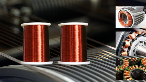
1.1 Definition and Key Functions of Magnet Wire Enamel InsulationMagnet wire enamel insulation is a thin, uniform polymer coating (e.g., PE, PU, PAI) covering the conductor (copper/aluminum) surface. Its core functions are twofold: first, to insulate the conductor from the external environment and prevent short-circuit faults; second, to reduce energy loss during current transmission and ensure efficient motor operation.
The performance of the insulation layer directly determines the application scenarios and service life of the magnet wire, and these performances must be verified through professional testing. The core dimensions include heat resistance, dielectric strength, abrasion resistance, adhesion, and chemical resistance. The performance requirements for the insulation layer vary significantly across different end applications. For example, magnet wire used in new energy vehicle motors requires high heat resistance and corona resistance, while magnet wire used in household appliances focuses more on the balance between cost and basic insulation performance.
1.2 Core Objectives of Magnet Wire Enamel Insulation TestingConducting insulation testing is not merely a "compliance process" but a quality control measure throughout the entire production and application chain. The core objectives include:
1. Ensure compliance with global standards (IEC, UL, ASTM) to obtain market access qualifications;
2. Verify the durability of the insulation layer under actual operating conditions (high temperature, vibration, humidity);
3. Avoid premature failure of end products (motors, transformers, generators);
4. Optimize production processes (e.g., enamel application, curing) to reduce defects;
5. Establish a trust barrier by means of transparent testing data and quality control systems to enhance buyers' confidence in cooperation.
 1.3 Interpretation of Core Terminology for Insulation Testing (Essential for Beginners)
Before understanding the testing methods, it is necessary to master the following key terms to avoid testing deviations caused by confusion of professional nouns:
- Dielectric Strength: The maximum voltage that the insulation layer can withstand before breakdown, which is the core indicator for measuring insulation performance;
- Pinhole: A tiny defect on the surface of the insulation layer that easily causes current leakage and is an important hidden danger leading to short circuits;
- Abrasion Resistance: The ability of the insulation layer to resist mechanical wear during winding and operation;
- Adhesion: The bonding strength between the insulation layer and the conductor, which directly affects whether paint peeling occurs during winding;
- Thermal Class: The maximum temperature that the insulation layer can withstand during long-term stable operation, with common classes such as Class 130, Class 180, and Class 220.
II. Unignorable Global Standards for Insulation TestingThe core premise of insulation testing is compliance with industry standards. Different regions and application scenarios correspond to different standard requirements. Accurately matching standards can ensure the validity of test results and the market compatibility of products.
2.1 IEC 60317 Series: The Global Benchmark for Magnet Wire TestingThe IEC 60317 series standards are the core reference for magnet wire testing worldwide, covering key requirements for insulation testing, including dielectric strength, pinhole detection, thermal aging, and other core items. This standard formulates differentiated testing methods for insulation layers of different materials (PE, PU, PAI, PI). For example, for high-temperature resistant PAI insulation layers, the temperature and duration requirements for thermal aging testing are much higher than those for ordinary PE insulation layers.
For magnet wire products targeting the global market, compliance with the IEC 60317 series standards is a basic requirement and a "passport" for entering most national markets.
2.2 UL 1446: The Core of Compliance for the North American MarketIf products are planned to enter the North American market, they must comply with the requirements of UL 1446 standard. The key testing focuses of this standard on insulation layers include voltage resistance performance and flame retardancy in critical application scenarios. Compared with IEC standards, UL 1446 pays more attention to the prevention and control of safety risks in the actual use of products, and its certification process is more rigorous, requiring manufacturers to provide complete test data and production process quality control documents.
It is recommended that magnet wire manufacturers targeting the North American market connect with UL certification bodies in advance to clarify testing details and certification processes, avoiding product backlogs due to non-compliance with standards.
2.3 ASTM Standards: Specialized Testing Basis for Industrial ApplicationsASTM standards formulate specialized insulation testing methods for the special needs of industrial scenarios. The most commonly used ones include ASTM D1676 (dielectric breakdown voltage testing) and ASTM D2307 (abrasion resistance testing). Compared with IEC and
UL standards, ASTM standards focus more on the accuracy of testing methods and the repeatability of data, and are suitable for magnet wire used in industrial motors and heavy-duty equipment with high requirements for insulation performance.
In practical applications, the corresponding standards should be selected according to the end scenarios of the products: IEC standards can be referred to for general scenarios, UL standards should be prioritized for the North American market, and ASTM standards should be met for high-end industrial scenarios.
2.4 Special Standards for Segmented Fields (New Energy, Aerospace, Medical)In addition to general standards, there are exclusive insulation testing requirements for special application fields:
- New Energy Vehicle Field: Must comply with the ISO/TS 16949 standard, which puts forward strict requirements for corona resistance and high-temperature aging testing of the enamel insulation layer of magnet wire used in drive motors;
- Aerospace Field: Must meet the MIL-STD military standard, and insulation testing needs to cover the performance stability under extreme high and low temperatures and vacuum environments;
- Medical Equipment Field: Must comply with relevant biocompatibility standards, and require the insulation layer to release no harmful substances during long-term use.
III. Step-by-Step Operation: Core Testing Methods for Magnet Wire Enamel InsulationThe following are the 6 most core and commonly used methods for magnet wire enamel insulation testing, covering key dimensions such as the electrical performance, mechanical performance, and environmental adaptability of the insulation layer. All have been verified by manufacturers in practice and can be directly applied to internal quality inspection or third-party testing.
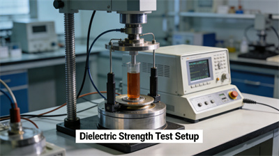
3.1 Dielectric Strength Test (Breakdown Voltage Test): Verify the Voltage Resistance of the Insulation LayerThe dielectric strength test is a core test to determine whether the insulation layer can withstand the rated voltage, directly reflecting the safety risk of the magnet wire during power-on operation.
Core Purpose: Measure the maximum voltage that the insulation layer can withstand before breakdown, ensuring that it does not fail under the actual working voltage.
Required Equipment: Dielectric testing instrument, electrode system (liquid electrode or solid electrode; liquid electrode is suitable for precise testing, and solid electrode is closer to actual working conditions).
Step-by-Step Process: 1. Sample Preparation: Cut an appropriately sized magnet wire sample, remove the oxide layer of the conductor at both ends, and ensure good electrode contact; 2. Voltage Application: Place the sample in the electrode system, select the voltage boosting method (ramp boosting or step boosting) according to standard requirements, and apply voltage at a constant speed; 3. Result Judgment: Record the voltage value when the insulation layer breaks down, and compare it with the minimum requirements of standards such as IEC 60317 (for example, the minimum breakdown voltage of magnet wire with a diameter of 0.5mm is usually 15kV).
Common Mistakes: Contamination on the electrode surface will cause deviations in test data and needs to be cleaned in advance; excessive voltage boosting speed is likely to lead to high test results, and the boosting rate must be strictly controlled according to standards.
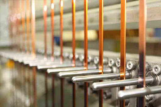
 3.2 Pinhole Detection (Spark Test): Identify Tiny Defect Hidden Dangers
Pinholes are common tiny defects in the magnet wire enamel insulation layer, which are difficult to detect with the naked eye but easily cause current leakage and then lead to motor short circuits. The spark test is an efficient method for detecting pinholes.
Core Purpose: Accurately identify pinhole defects on the insulation layer and control the defect density.
Required Equipment: Spark tester (can be divided into online type and offline type; online type is suitable for real-time detection during production, and offline type is suitable for sampling inspection of finished products), supporting adjustable voltage.
Step-by-Step Process: 1. Voltage Calibration: Adjust the test voltage according to the diameter of the magnet wire; the thicker the wire diameter, the higher the required test voltage (for example, the voltage for 0.3mm diameter is set to 8-10kV, and for 1.0mm diameter is set to 18-20kV); 2. Test Operation: Pass the magnet wire sample through the electrode area of the spark tester at a constant speed to ensure that the sample is completely covered in the electric field; 3. Defect Marking: If there is a pinhole in the insulation layer, current will generate a spark through the pinhole, and the tester will automatically alarm and mark the defect location.
Key Reminder: Even if there is only 1 pinhole per 100 meters, it may cause a short circuit fault in the terminal motor. Therefore, it is necessary to strictly control the pinhole defect rate, and qualified products usually require no visible pinholes.
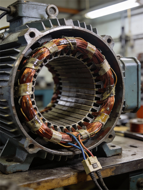
3.3 Abrasion Resistance Test: Ensure Mechanical Stability During Winding and OperationDuring motor winding, the magnet wire will rub against the wire slot and tooling, and may also suffer mechanical wear due to vibration during operation. Insufficient abrasion resistance will lead to damage and failure of the insulation layer.
Core Purpose: Verify the ability of the insulation layer to resist mechanical wear, ensuring that it does not break during winding and long-term operation.
Required Equipment: Abrasion resistance tester (commonly mandrel-type tester, equipped with weight-adjustable contact parts).
Step-by-Step Process: 1. Sample Fixing: Fix the magnet wire sample on the mandrel of the tester to simulate the actual winding state; 2. Wear Setting: Adjust the contact weight and wear cycle according to the product application scenario (for example, magnet wire used in new energy vehicle motors needs to increase the wear cycle); 3. Failure Judgment: Continuously monitor the voltage change of the sample during the wear process; when the voltage drops significantly, it indicates that the insulation layer is damaged, and record the wear times or time at this point.
Application Relevance: This test is particularly critical for magnet wire used in new energy vehicle motors and industrial heavy-duty equipment motors. Such scenarios have tighter winding and more severe vibration, requiring higher abrasion resistance of the insulation layer.
3.4 Adhesion Test (Peel Test): Ensure Tight Bonding Between Insulation Layer and ConductorInsufficient adhesion between the insulation layer and the conductor will lead to paint peeling and blistering during winding, which in turn causes insulation failure. The adhesion test is a core method to verify the bonding strength between the two.
Core Purpose: Measure the bonding strength between the insulation layer and the copper/aluminum conductor, ensuring no paint peeling during winding.
Required Equipment: Tensile testing instrument, peel fixture (adapted to magnet wire samples of different diameters).
Step-by-Step Process: 1. Sample Preparation: Cut a magnet wire sample, peel off part of the insulation layer at one end to expose the conductor, and ensure the peeling length meets the standard requirements; 2. Fixing and Clamping: Fix the conductor end and insulation layer end of the sample in the upper and lower fixtures of the tensile tester respectively; 3. Test Execution: Start the tester, stretch the sample at a constant speed, and record the maximum pull force when the insulation layer is peeled off; 4. Result Judgment: Compare with the minimum standard requirements (for example, the minimum peel force of PAI insulation layer is usually 5N); those below the standard are unqualified.
Risk Warning: Magnet wire with poor adhesion will have a significantly increased paint peeling rate during automatic winding, which not only increases the production scrap rate but also may cause potential safety hazards in the finished motor.
3.5 Thermal Aging Test: Verify Durability Under High-Temperature Working ConditionsDuring motor operation, the magnet wire will generate heat. High-temperature environments will accelerate the aging of the insulation layer and shorten its service life. The thermal aging test can simulate long-term high-temperature working conditions and predict the service life of the insulation layer.
Core Purpose: Evaluate the performance stability of the insulation layer under long-term high-temperature environments and verify whether its thermal class meets the requirements.
Required Equipment: Aging oven (supporting precise temperature control), temperature controller, dielectric testing instrument (for performance retesting after aging).
Step-by-Step Process: 1. Aging Setting: Set the aging temperature according to the thermal class of the magnet wire (for example, 180°C for Class 180 magnet wire), and set the aging duration at the same time (the standard aging duration is usually 1000 hours, and accelerated aging can shorten the test cycle); 2. Sample Aging: Put the magnet wire sample into the aging oven, keep the temperature stable, and complete the set aging duration; 3. Performance Retesting: Take out the aged sample, cool it to room temperature, and retest its core performances such as dielectric strength and adhesion; 4. Result Judgment: If the retested performance still meets the standard requirements, it indicates that the thermal aging performance of the insulation layer is qualified and can meet the needs of long-term high-temperature working conditions.
Key Technology: The actual service life of the magnet wire can be quickly predicted through accelerated aging testing. For example, aging at 200°C for 100 hours can simulate the service state at 180°C for more than 10 years, greatly shortening the test cycle.
3.6 Chemical Resistance Test: Adapt to Special Environment ApplicationsSome magnet wire application scenarios will come into contact with oil stains, cooling fluids, humid environments, or corrosive gases (such as marine environments, chemical equipment, and automotive engine compartments). Chemical resistance testing is required to verify the environmental adaptability of the insulation layer.
Core Purpose: Test the performance stability of the insulation layer in specific chemical environments to ensure that it is not corroded and failed.
Required Equipment: Chemical bath, environmental test chamber, dielectric testing instrument.
Step-by-Step Process: 1. Environment Simulation: Configure the corresponding chemical medium (such as engine oil, cooling fluid, salt water, etc.) in the chemical bath according to the actual application scenario, or set the humid and corrosive gas environment in the environmental test chamber; 2. Sample Exposure: Immerse the magnet wire sample in the chemical medium or place it in the set environmental test chamber, and control the exposure duration according to standard requirements; 3. Performance Evaluation: After taking out the sample, test its dielectric strength, adhesion and other performances, and observe whether there are bulges, cracks, peeling and other phenomena on the surface of the insulation layer; 4. Result Judgment: If there is no significant performance degradation and no surface abnormalities, it indicates that the chemical resistance is qualified.
Application Focus: This test is mainly aimed at magnet wire used in special environment applications. For example, magnet wire used in marine motors needs to focus on salt water corrosion resistance testing, and magnet wire used in automotive engine compartments needs to be tested for engine oil and high-temperature cooling fluid resistance.
IV. Guide to Testing Equipment Selection: Procurement and Usage Suggestions for ManufacturersSelecting appropriate testing equipment is the basis for ensuring accurate and efficient test results. Manufacturers of different scales (small and medium-sized vs. large-scale high-end production) have great differences in equipment needs, and it is necessary to reasonably select models based on their own production capacity and product positioning.
4.1 Internal Testing vs. Third-Party Testing: Pros and Cons Comparison and Combination StrategyManufacturers can choose internal testing, third-party testing, or adopt a hybrid mode of "internal + third-party" according to their own needs:
Advantages of Internal Testing: Short test cycle, real-time feedback on production process quality, suitable for process control of high-capacity production; lower cost in the long run, and rapid optimization of production processes. Disadvantages: Need to invest in equipment procurement and personnel training costs; some high-end testing items are difficult to cover.
Advantages of Third-Party Testing: Professional qualifications, high authority of test results, suitable for product certification, customer audits and other scenarios; access to high-end professional equipment to cover special testing items. Disadvantages: Long test cycle, high cost per test, unable to guide production in real time.
Hybrid Strategy Suggestion: Incorporate basic items such as dielectric strength testing and spark testing into internal testing to achieve real-time control of the production process; entrust high-end items such as thermal aging testing and chemical resistance testing or tests required for certification to third-party institutions to balance control efficiency and compliance.
4.2 Essential Basic Equipment for Small and Medium-Sized ManufacturersSmall and medium-sized manufacturers mainly produce basic products, and can give priority to configuring the following entry-level equipment to meet core testing needs:
Core Equipment List: Portable spark tester (suitable for sampling inspection of finished products, affordable price, simple operation), basic dielectric testing instrument (meeting regular voltage testing needs), manual abrasion resistance tester (simple structure, low maintenance cost).
Cost Reference: The budget for this set of equipment is about 5,000-20,000 US dollars, which can cover more than 80% of basic testing needs.
Must-Have Functions: The equipment must have calibration certification qualifications to ensure accurate test data; support adaptation to multiple wire diameters to meet the testing needs of different products; the operation interface is simple and easy to understand, reducing personnel training costs.
4.3 Essential Advanced Equipment for Large-Scale High-End ProductionLarge-scale high-end production (such as magnet wire for new energy vehicles and aerospace) has higher requirements for testing efficiency and accuracy, and needs to be equipped with advanced equipment:
Core Equipment List: Online spark testing system (can be integrated into the production line to realize real-time detection and defect marking, improving production efficiency), automatic thermal aging oven (can test multiple samples at the same time, high temperature control accuracy, supporting program temperature rise), data logging software (real-time tracking of test data, analysis of production trends, and realization of quality traceability).
Core Advantages: Online equipment can prevent unqualified products from flowing into the next process, reducing the scrap rate; automatic equipment reduces human operation errors, and test data is more accurate; data logging software helps optimize production processes and improve product quality stability.
4.4 Equipment Calibration and Maintenance: The Key to Ensuring Accurate TestingThe calibration and maintenance of testing equipment directly affect the accuracy of test results and must be carried out in strict accordance with requirements:
Regular Calibration: In accordance with the requirements of the ISO 9001 standard, entrust professional institutions to calibrate the testing equipment regularly to ensure that the equipment accuracy meets the standards. Calibration records must be properly kept for customer audits.
Daily Maintenance: 1. The electrode system needs to be cleaned regularly to avoid test deviations caused by contamination; 2. Equipment such as aging ovens and environmental test chambers need to regularly check temperature uniformity and replace aging parts in a timely manner; 3. Testing instruments should avoid humid and dusty environments and be stored in a dry and ventilated place.
Common Mistakes: Using expired calibration standards for equipment calibration will lead to distorted test data; ignoring daily equipment maintenance is likely to cause equipment failures and affect test progress.
V. Common Mistakes in Insulation Testing and Pitfall Avoidance GuidelinesIn the actual testing process, many detailed problems will lead to deviations in test results and even mislead production decisions. The following are the 5 most common mistakes made by manufacturers and corresponding avoidance methods:
Mistake 1: Improper setting of test voltage. Too low voltage will miss insulation layer defects, while too high voltage will cause "false breakdown", leading to qualified products being misjudged as unqualified. Avoidance Method: Strictly calibrate the test voltage according to the magnet wire diameter and standard requirements; different wire diameters correspond to different voltage ranges, and random adjustment is prohibited.
Mistake 2: Non-standard sample preparation. For example, conductor oxidation at both ends of the sample, surface contamination, or non-compliant peeling length will all affect test data. Avoidance Method: Formulate a standardized sample preparation process, clarify the sample cutting length, oxide layer treatment method, peeling length and other requirements, and check the sample status before testing.
Mistake 3: Ignoring the impact of environmental factors. Humidity and temperature in the test environment will affect test results such as dielectric strength (for example, a high-humidity environment will reduce the breakdown voltage of the insulation layer). Avoidance Method: Control the test environment within the range required by standards (usually temperature 23±2℃, humidity 50±5%), and record environmental parameters in the test report.
Mistake 4: Misjudgment of test results. For example, confusing "dielectric leakage" with "breakdown", leading to the elimination of qualified products. Avoidance Method: Train testers to master standard judgment criteria, clarify the difference between leakage current and breakdown current; conduct third-party test review for controversial samples.
Mistake 5: Omitting test records. Some manufacturers omit test data records to save time, which makes it impossible to achieve quality traceability and difficult to locate the cause of subsequent problems. Avoidance Method: Establish a complete test record system, detailedly record sample information, test equipment, test parameters, test results, etc., and the records need to be retained for a long time.
 VI. Conclusion: Building the Foundation of Magnet Wire Quality Through Scientific Testing
The quality of the magnet wire enamel insulation layer directly determines the safety and reliability of end products, and scientific testing methods are the core means to control the quality of the insulation layer. For manufacturers, mastering the basic cognition, core methods, standard requirements and equipment selection skills of insulation testing can not only improve product quality and reduce failure risks but also enhance the core competitiveness in the market.
It is recommended that manufacturers establish a personalized testing system combined with their own product positioning and application scenarios, integrate testing into the entire production process, and avoid quality hazards from the source. If encountering technical difficulties during the testing process, they can rely on the technical support of professional magnet wire suppliers to accurately solve the pain points in testing and production.